It’s about time I created something noteworthy, after joining a Lowell Makes over two years ago.
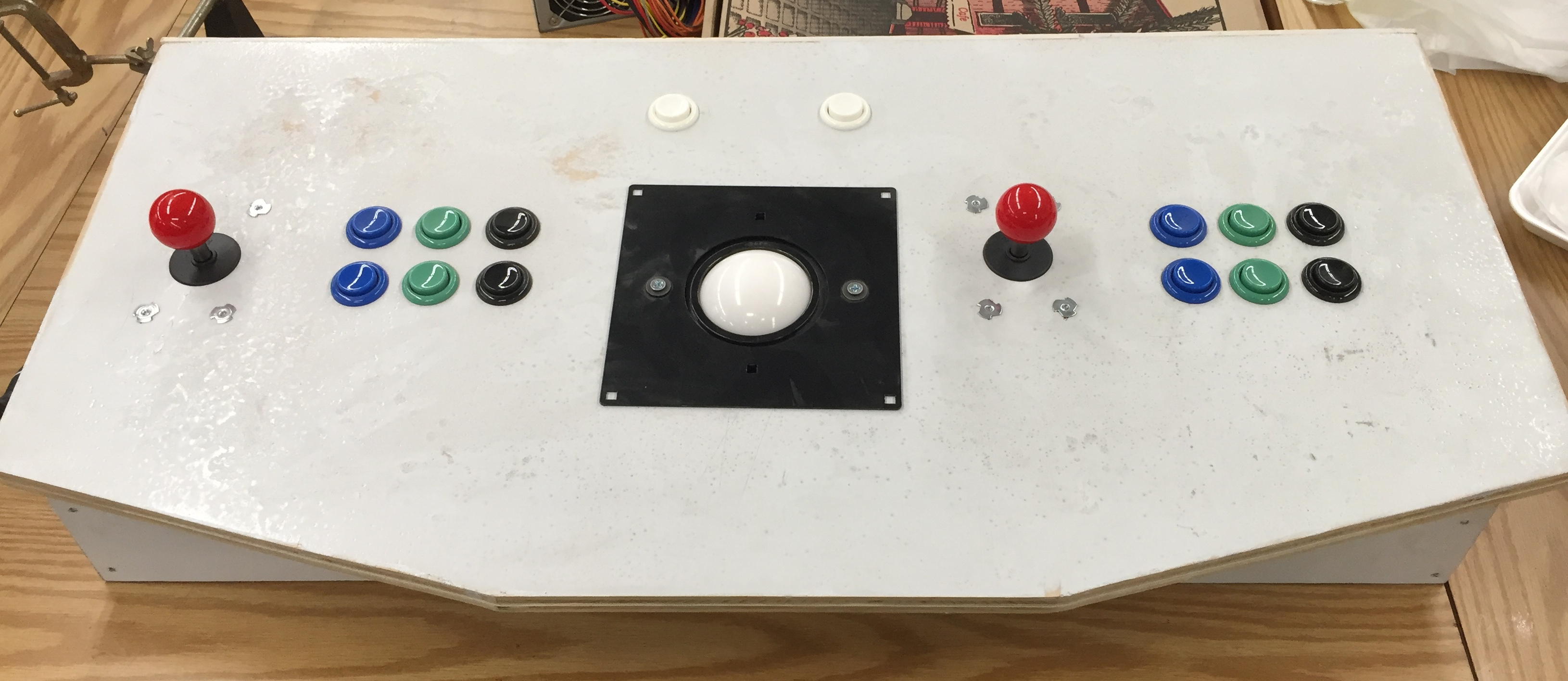
Like most DIY posts nowadays, I’m leading off with the finished product: a mostly functional arcade control panel!
I had a ton of help in basic woodworking skills from a few members in the makerspace.
- Jack Walsh – How to cut shit on the table saw without murdering myself
- Bill Taylor – Jigsawing for dummies
- Steve Birmingham – More tablesaw tutelage, plus making my mitred edges actually fit
- Chris Donius – Helping me put the damned thing together
- Castro-Yves Arboite – Helping me with pictures and general artistic guidance
I sourced the parts from all over.
- Birch plywood – Home Depot
- Buttons, Joysticks – Sparkfun
- Track ball and plate – E-bay auctions
- T-molding – T-molding.com
With the aid and advice of my fellow makerspace members, this was built almost entirely from scratch. Here’s a quick rundown of the build process.
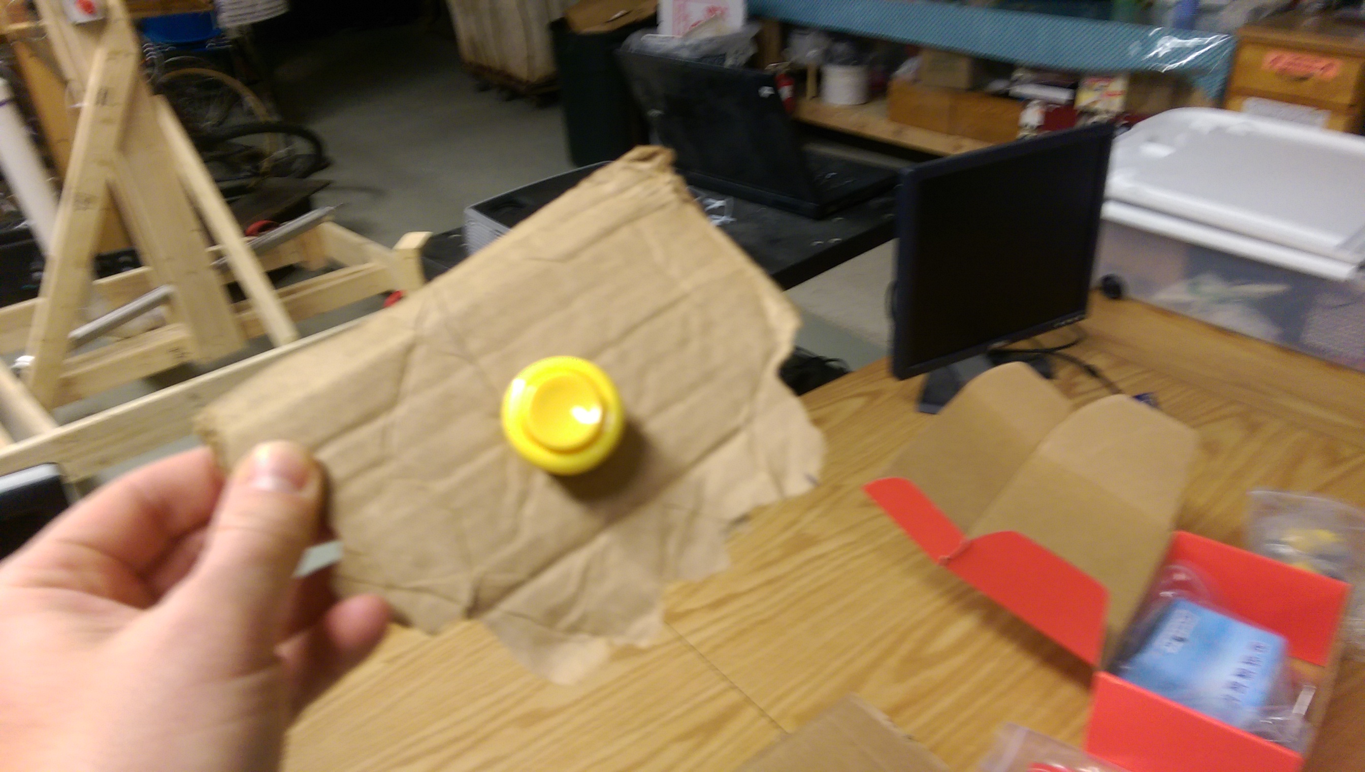
I tested the button on cardboard. I don’t remember why I thought this would be important or useful. But I did.
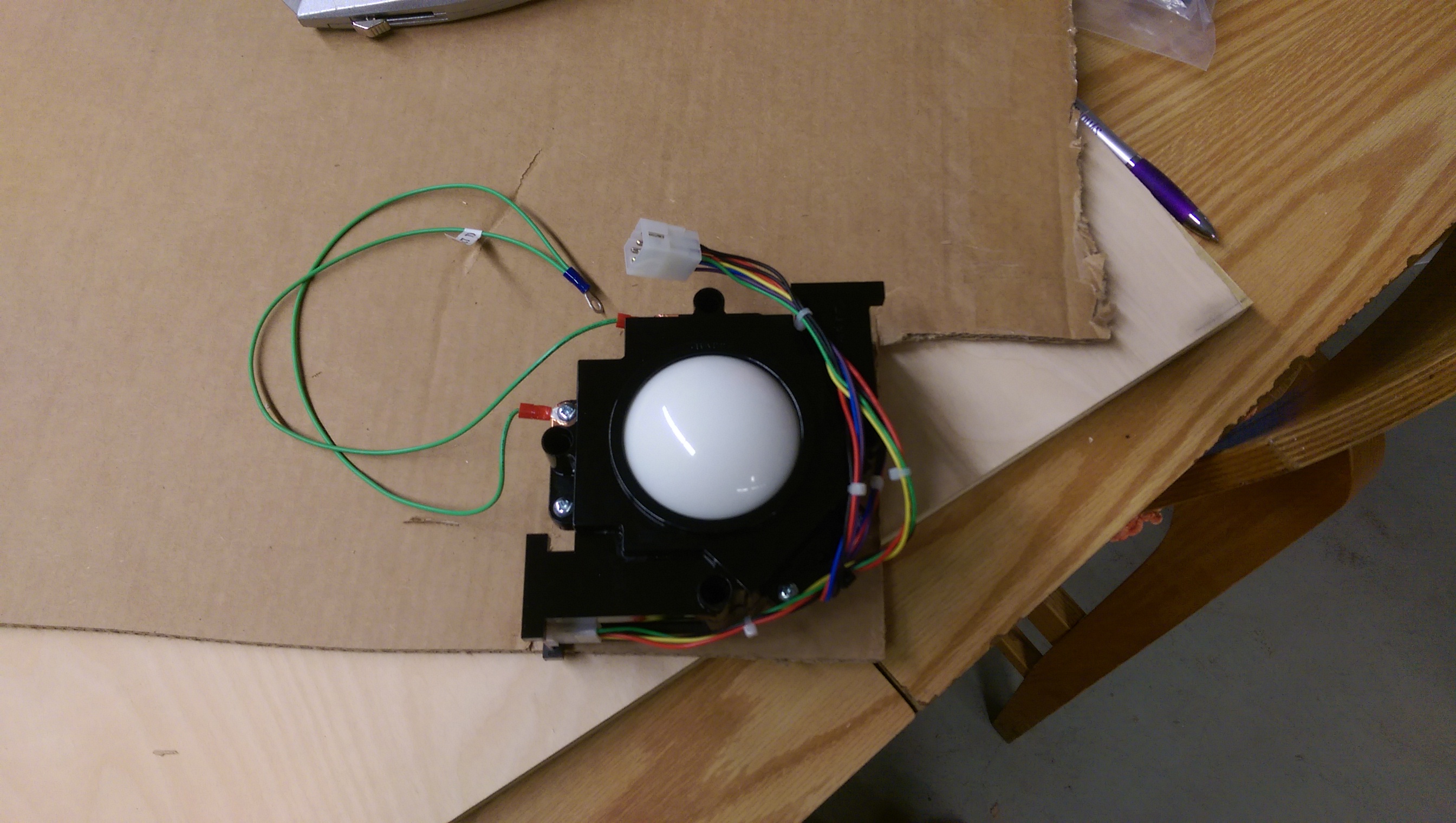
My initial plan was to trace out the guide for the top panel layout on cardboard and cut out the holes. But it turns out cutting a straight line on corrugated board is fucking impossible and I just gave up and went straight to pencil on the wood.
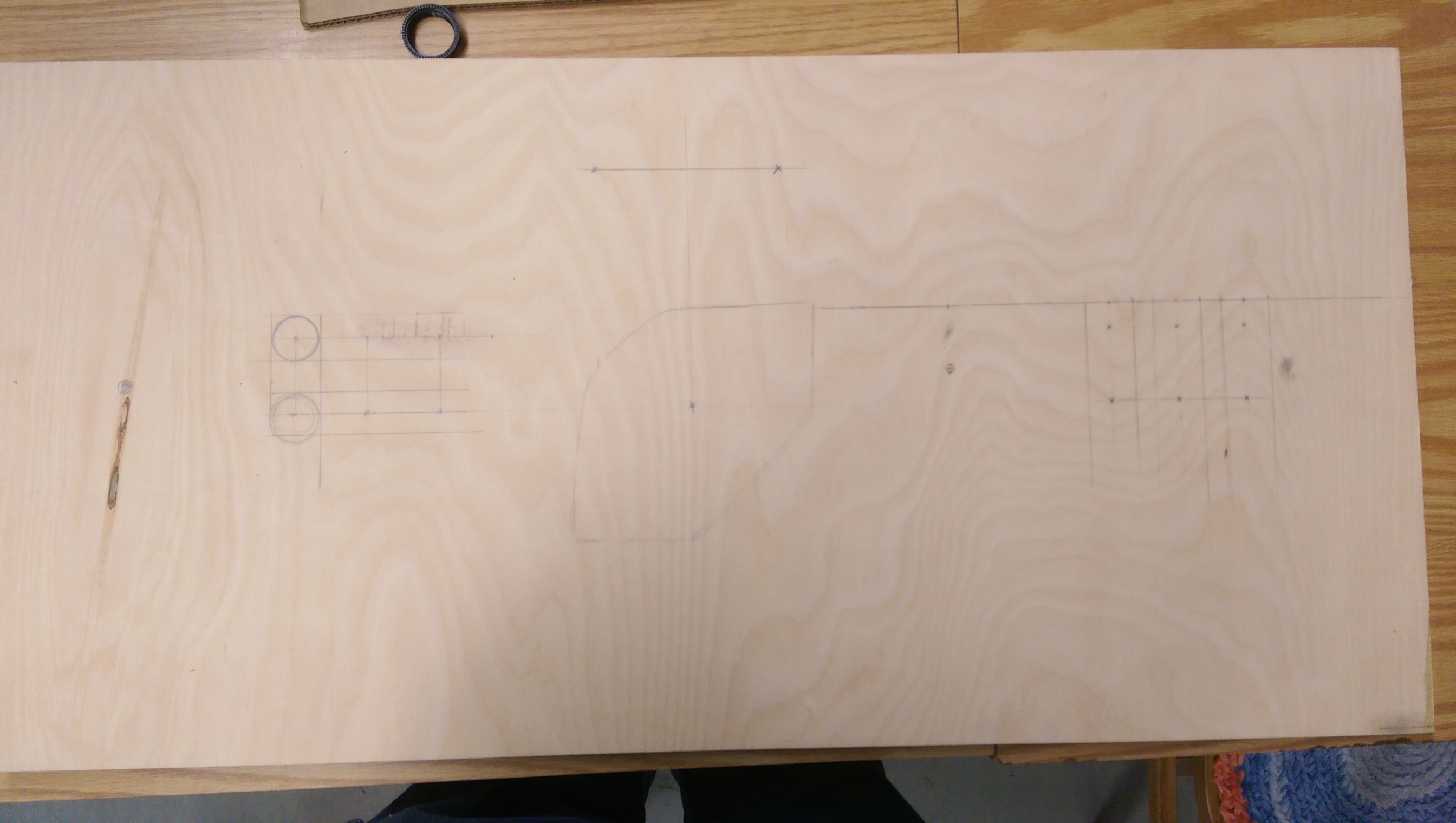
I was told later that I could have made the process easier by tracing a guide and then folding it over halfway, seeing as it’s symmetrical. Oh well. Live and learn.
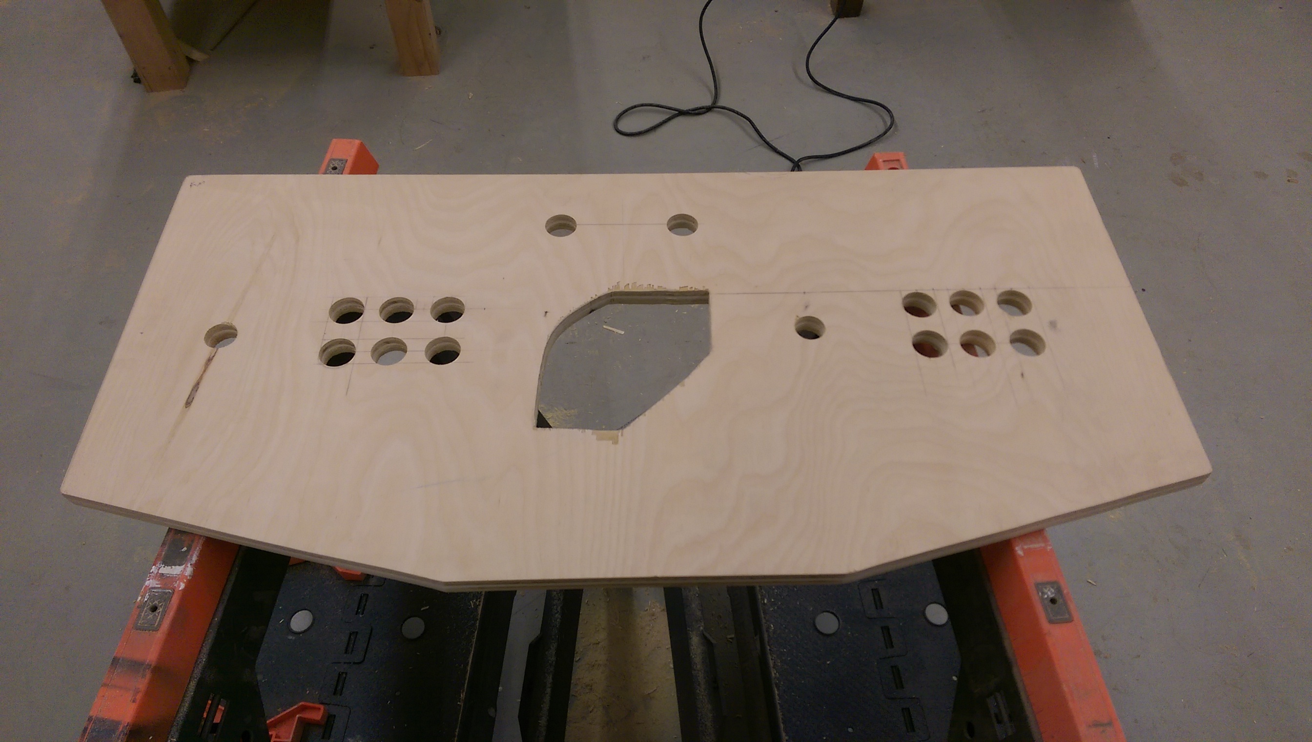
Finished top panel. Everything was going smoothly (pun intended) but then I bungled the trackball hole jigsawing, and got mad splintering everywhere. Yeah, that again. A little putty should patch it up. It’s getting painted (or maybe even laminated) later, so I’m really trying not to sweat it. The Forstner cuts for the button and joystick holes came out gorgeous, though, didn’t they?
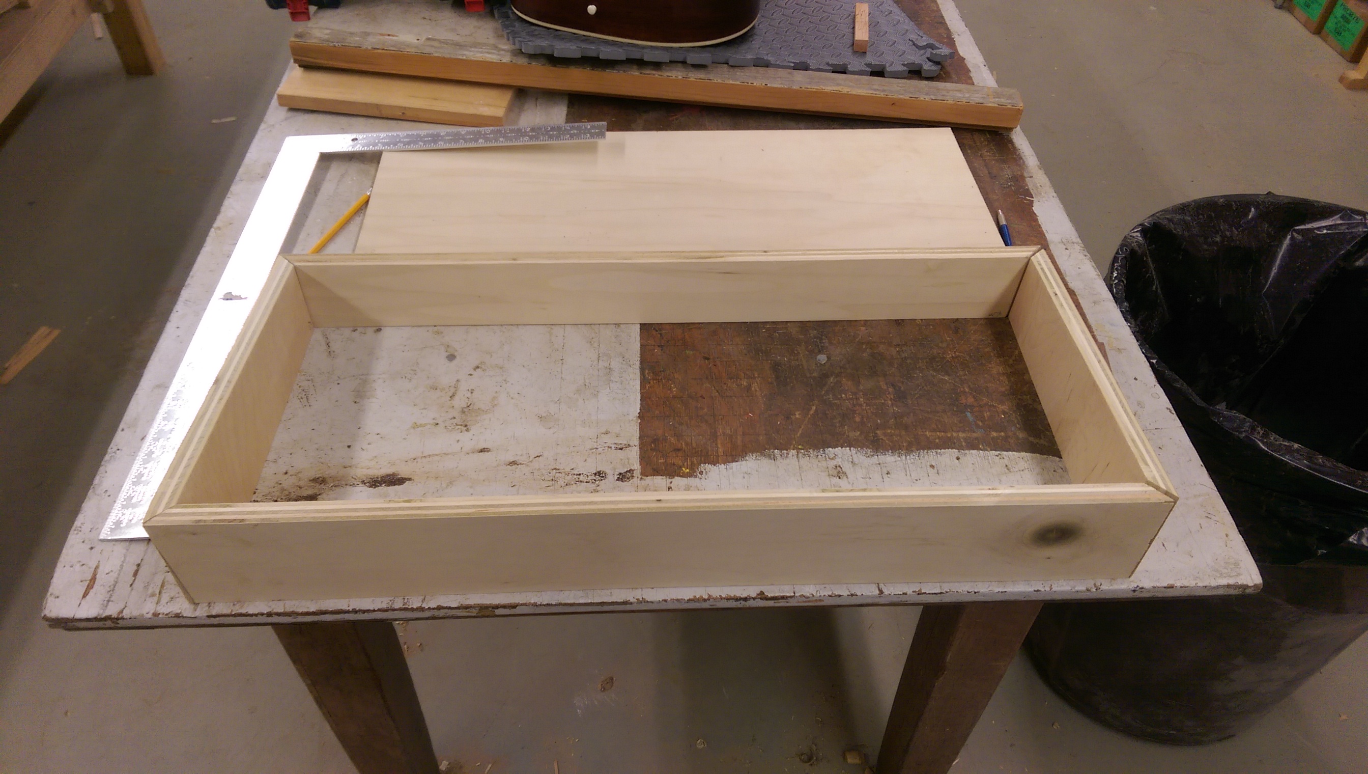
The sides all meet at “mitred” edges, with the intention being to show no end grain wood. This worked, but was a gigantic fucking pain in the ass because to fit this together, the angles need to be almost perfect. Like, to the millimeter. You can see I didn’t get it quite exactly right, but settled for a level of imperfection that’s invisible to the user (messy insides).
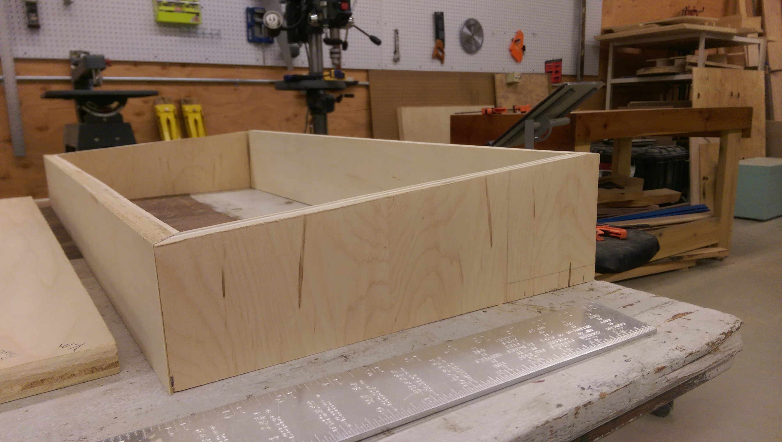
The panel needs to be tilted towards the player. So the back is taller than the front, and the sides have angled top edges. Wound up doing more trigonometry than I would have expected.
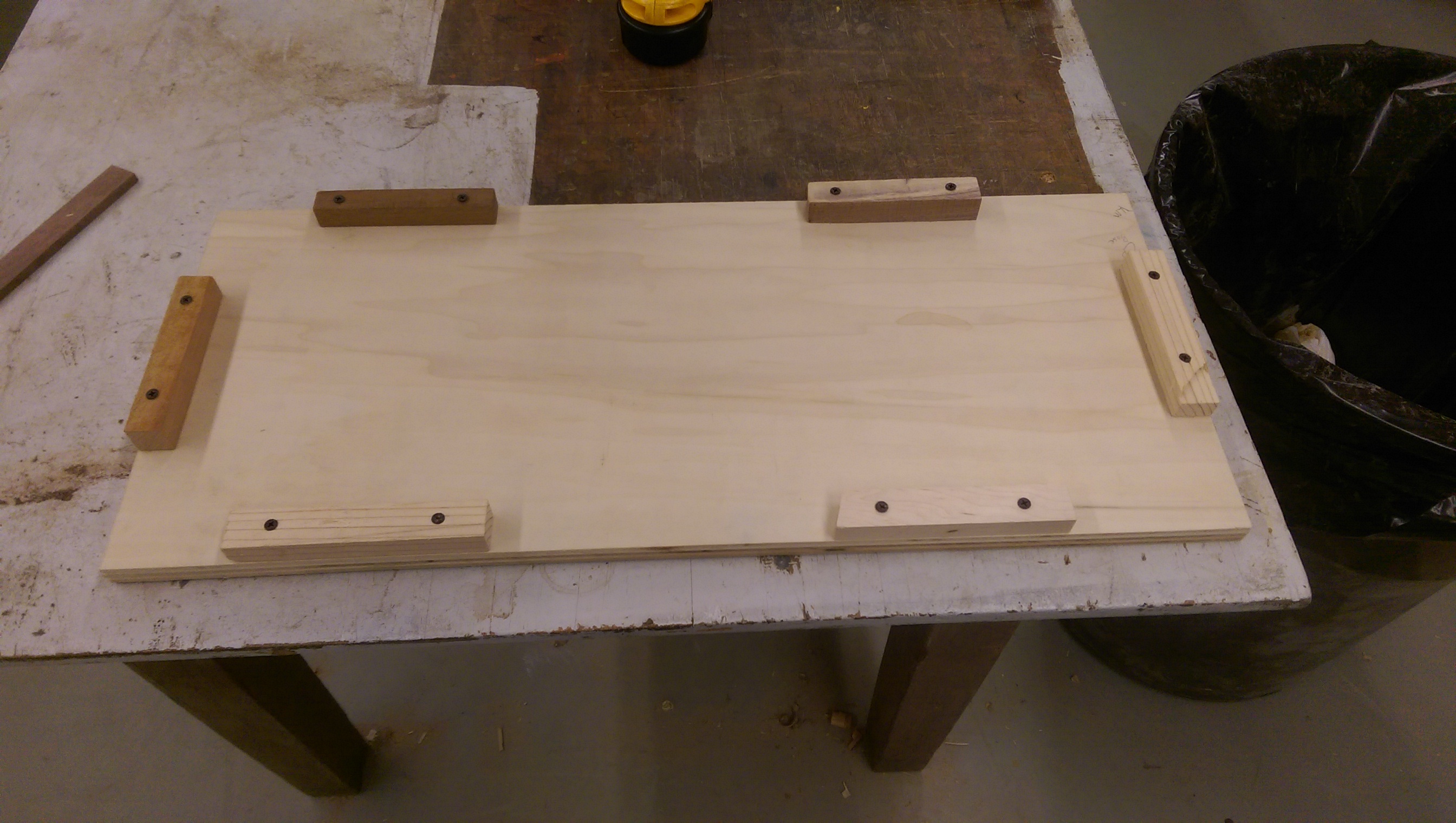
The base. The little pieces along the side are called “ledger boards” and they are what I used to attach the base to the sides without exposing any screw holes. I grabbed them from random scraps around the space, which is why they are all different colors. One of them turned out to be maple, which apparently has the same chemical properties as adamantium. Whoops.
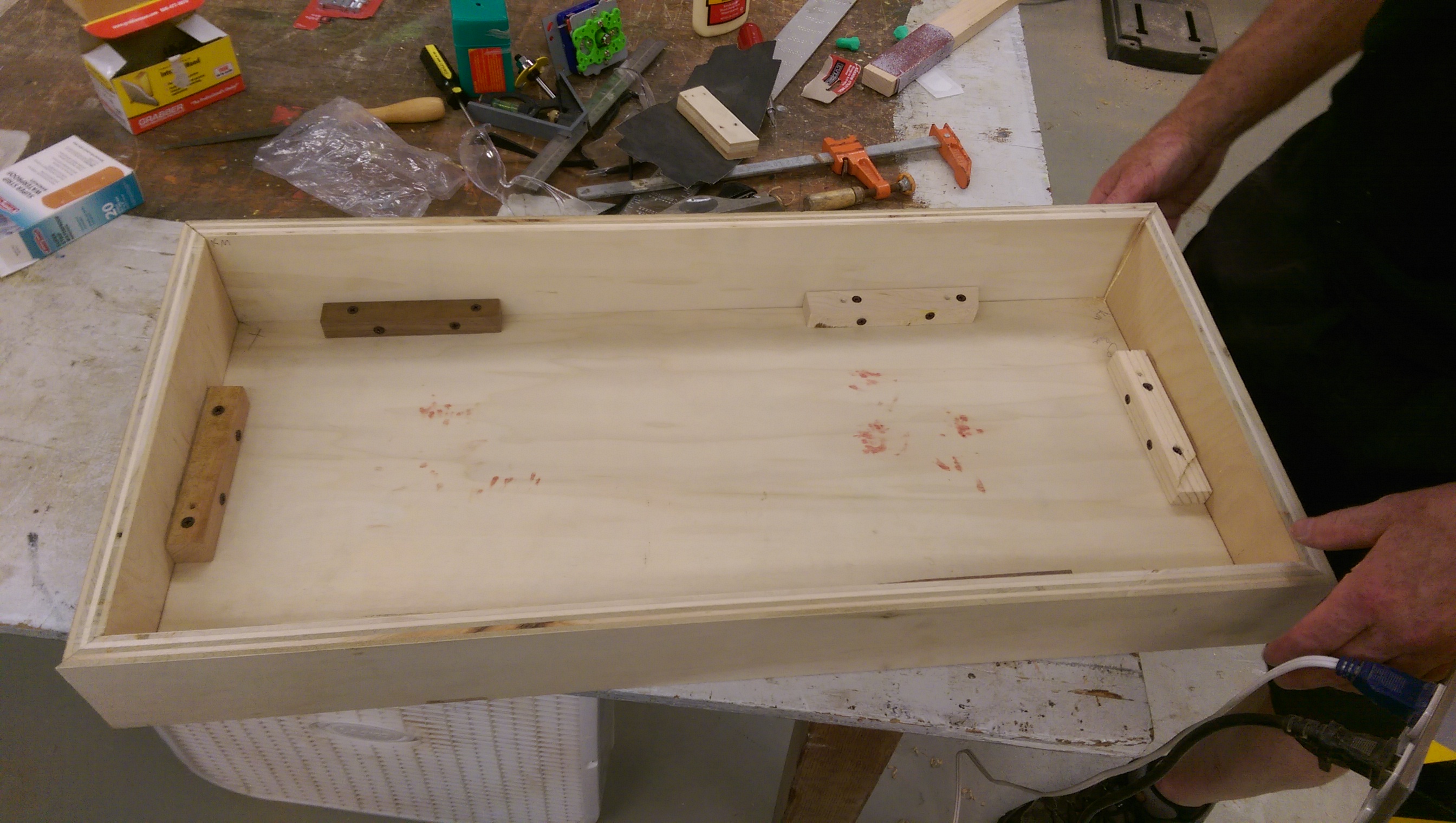
Attaching the sides to the base via the ledger boards. Chris bled on it. My fault, really, for picking those pieces out of particularly dense wood.
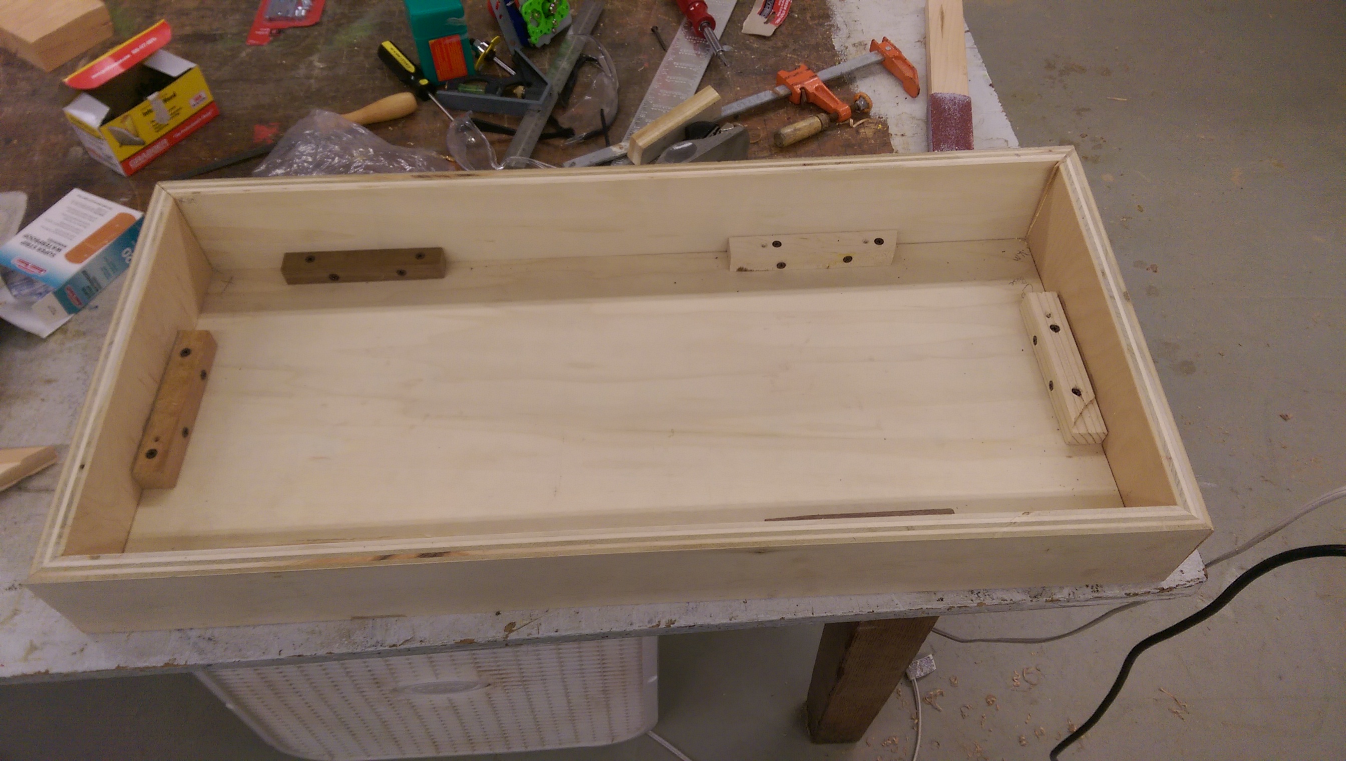
Nothing a little sanding couldn’t fix!
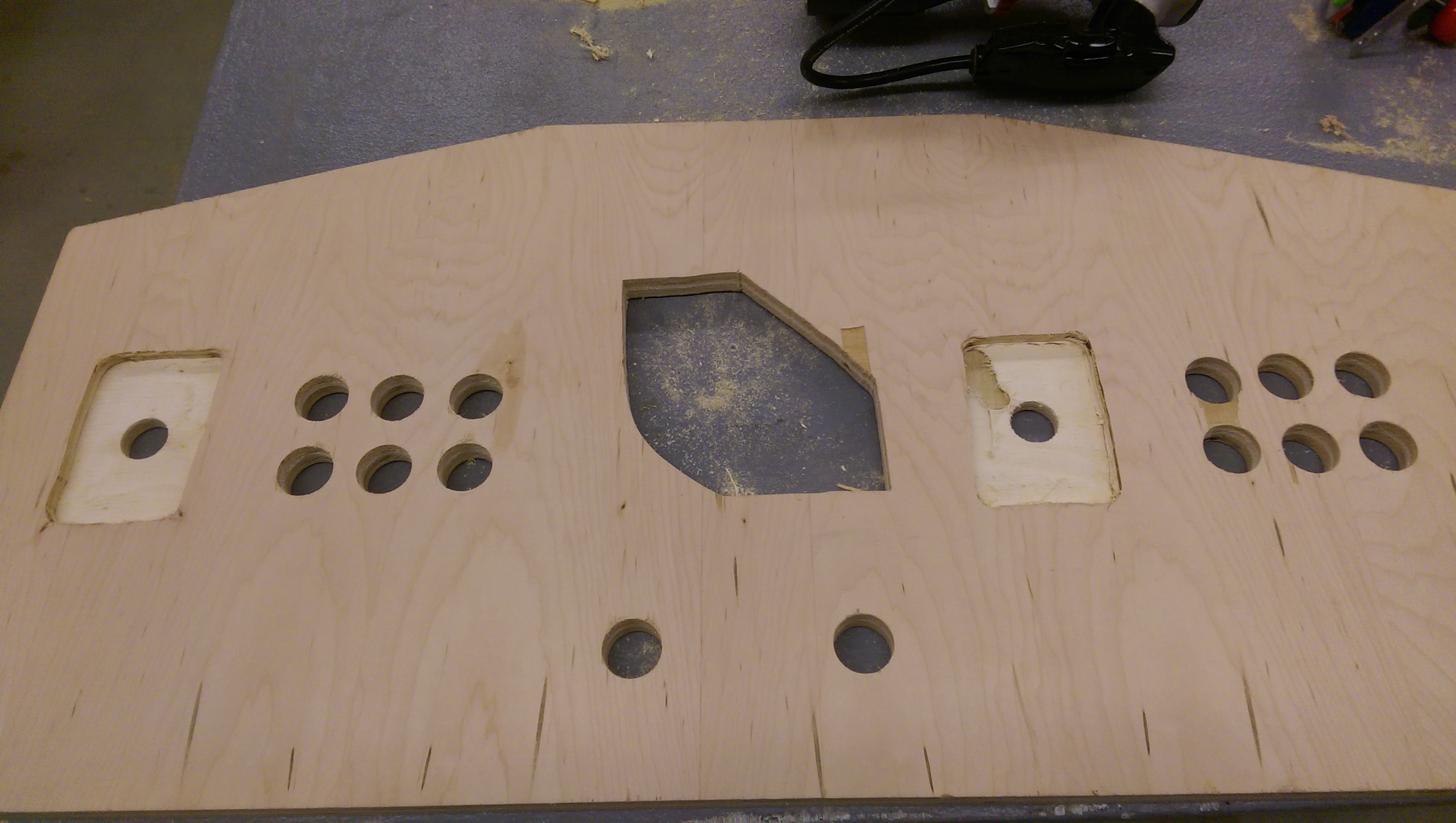
Did I say the top was finished? Because it wasn’t. I had to use a router to cut out some of the wood around the joystick holes, on the underside. This is necessary to give the joysticks a little more height, by giving it ⅜” of wood to get through, instead of ¾”. The one on the left came out perfectly. The one on the right went to shit because the router bit wasn’t properly tightened and dropped a smidge at the last second. Oh well, another invisible flaw.
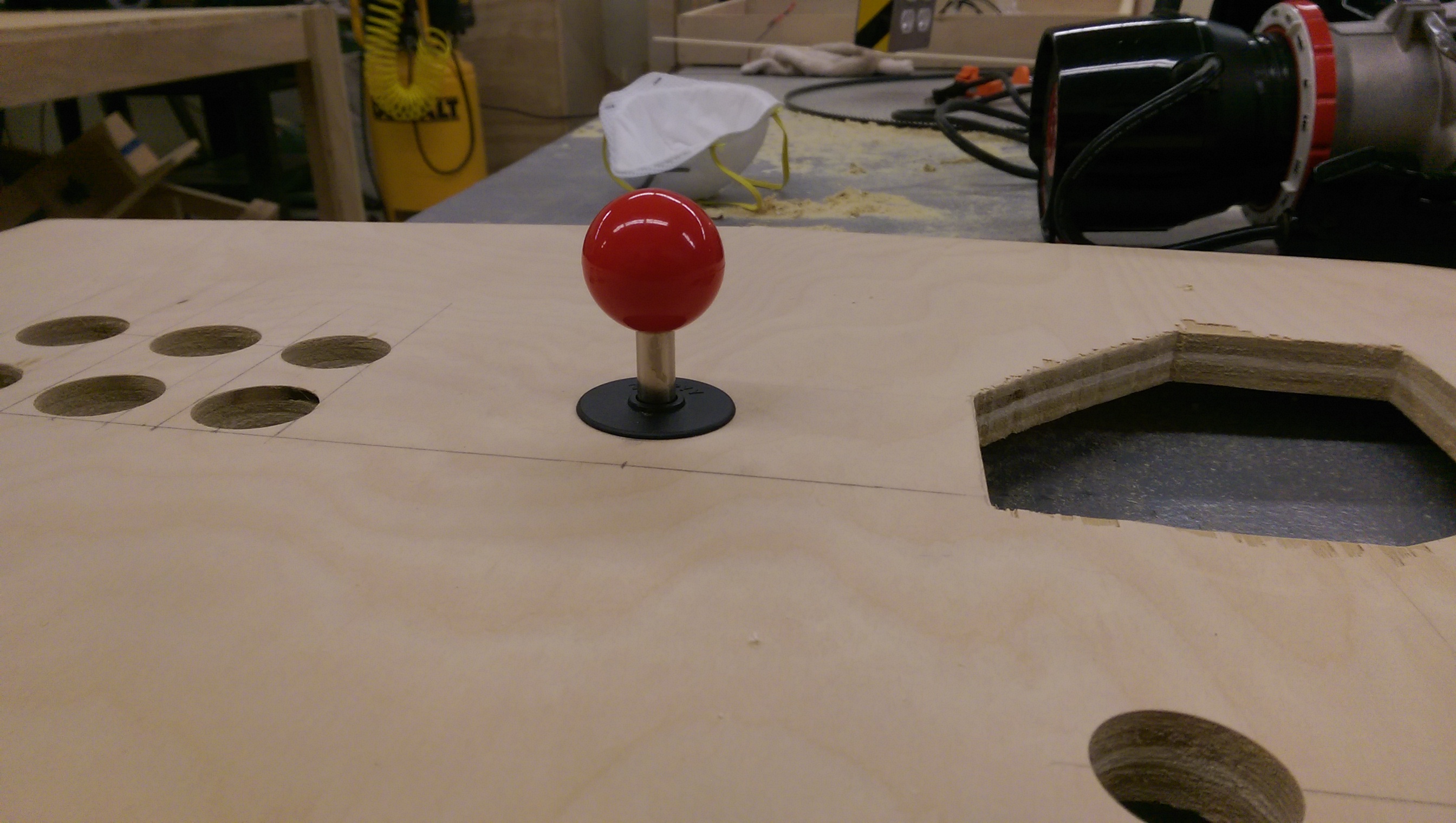
Stand proud, little stick.
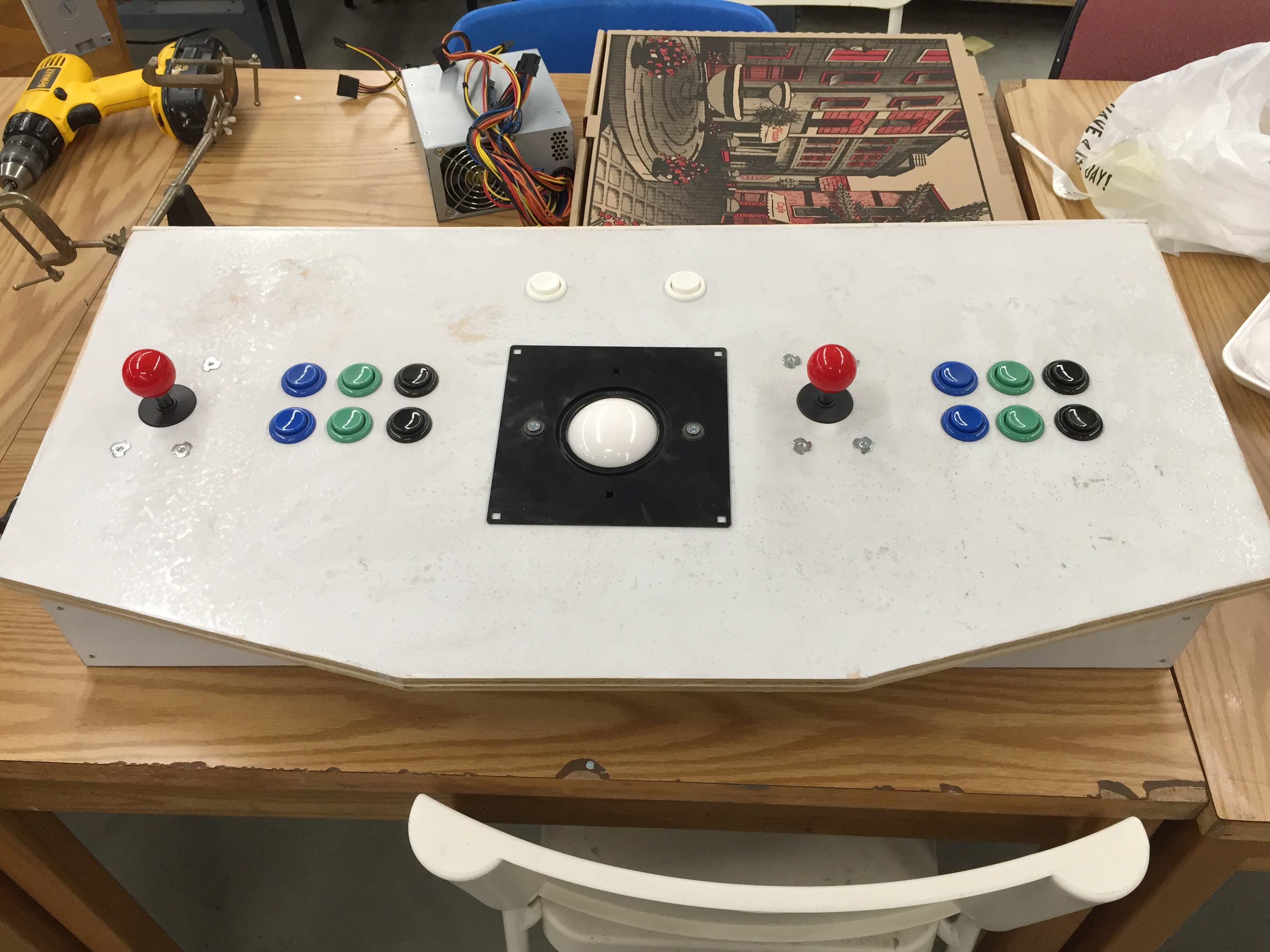
I didn’t take enough pictures of the rest of the assembly process, but it’s pretty straightforward. Hinges hold the top in place along the back edge. Buttons and joysticks take their places: the buttons are just tightened by plastic nuts and are easy enough to remove, the joysticks are screwed from below.
I tried to spray paint the exterior, but apparently some part of the spray painting process escapes me because the paint came out in shitty bursts and so it kind of came out looking like spotty garbage. I’ll go over it again later. Kind of gives it a beat up aesthetic in the meantime.
Now, how does it all work?
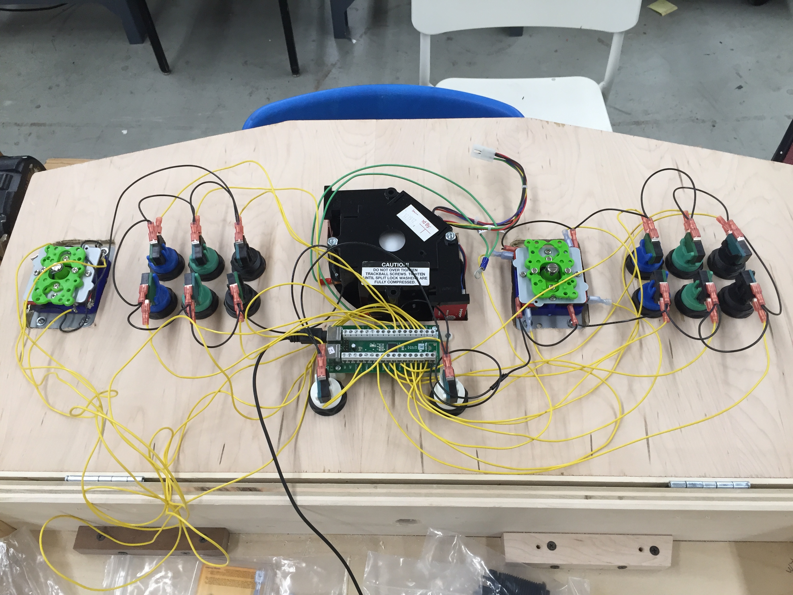
The buttons connect to a board called the IPAC-32 as TTL. Which basically means there’s no need for me to worry about impedance or current or any of that analog crap. One terminal of each button and joystick switch gets sent to a dedicated terminal on the IPAC, and the other ones share the same ground wire on a loop. The IPAC converts the On/Off button transitions into simple keyboard scan codes, and connects to the host machine via USB. So, as far as the host sees, it’s just getting keyboard presses/releases from the panel.
The nice thing about the end result is that it’s so encapsulated. It’s only output is a USB cable, so it really just looks like any other plug-in peripheral. As such, it was easy to test. Just plug in a Raspberry Pi with some emulation software on it, configure it for keyboard input (harder than it should have been), and give it a go. A few minutes later, Snake Man was toast and I had myself a confirmed functioning control panel.
I may add some video or stills of gameplay in action, if people are interested.
This is a standalone component of a much larger project.